Building a 49–470 MHz 15-Element Twin-Boom LPDA
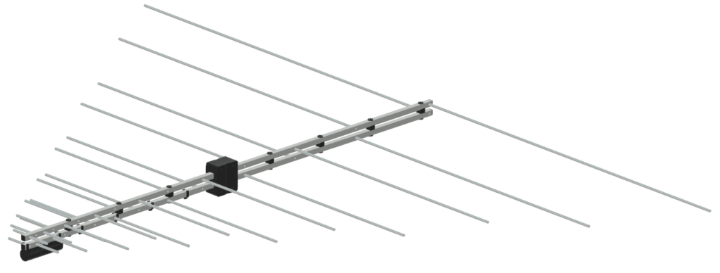
I’ve decided it’s time to build a proper wideband directional antenna that actually covers 6 m through 70 cm in one package. After running the numbers, I’ve settled on a 15-element Log Periodic Dipole Array (LPDA) and will be starting construction over the coming weeks.
Project Goals
- Frequency coverage: 49–470 MHz (continuous)
- Solid gain and front-to-back ratio across the whole range
- Reliable twin-boom design with good mechanical strength
- Heavy use of 3D printing (PETG CF) for custom parts
- All hardware in stainless steel
- Easy to replicate for other hams
Design Overview
The design comes from a professional LPDA calculator with the following key parameters:
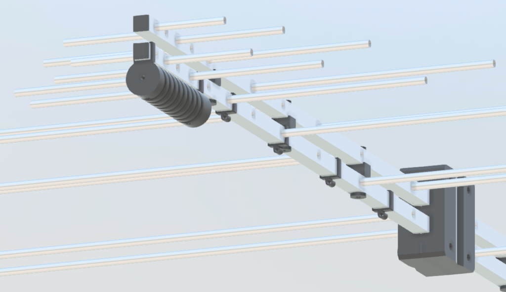
- 15 elements
- Boom length: 1.96 m (main) + 765 mm rear extension for the terminating stub
- Twin 20×20 mm square aluminum booms
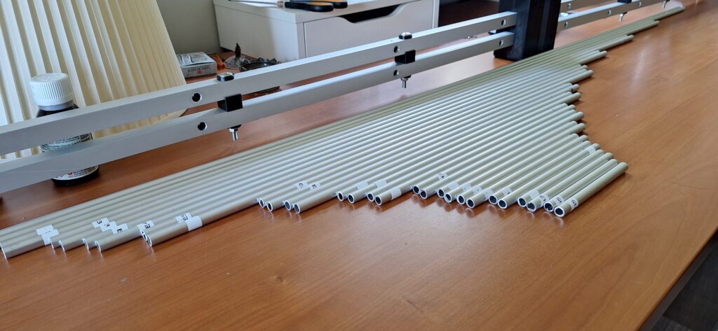
- Element diameter: 10 mm aluminum tube
- Target feeder impedance: ~115 Ω
I will be mounting the elements by pushing them all the way through the square booms until flush with the opposite wall, then securing them with stainless self-tapping screws. Half-element lengths have been adjusted accordingly.
Key Design Decisions
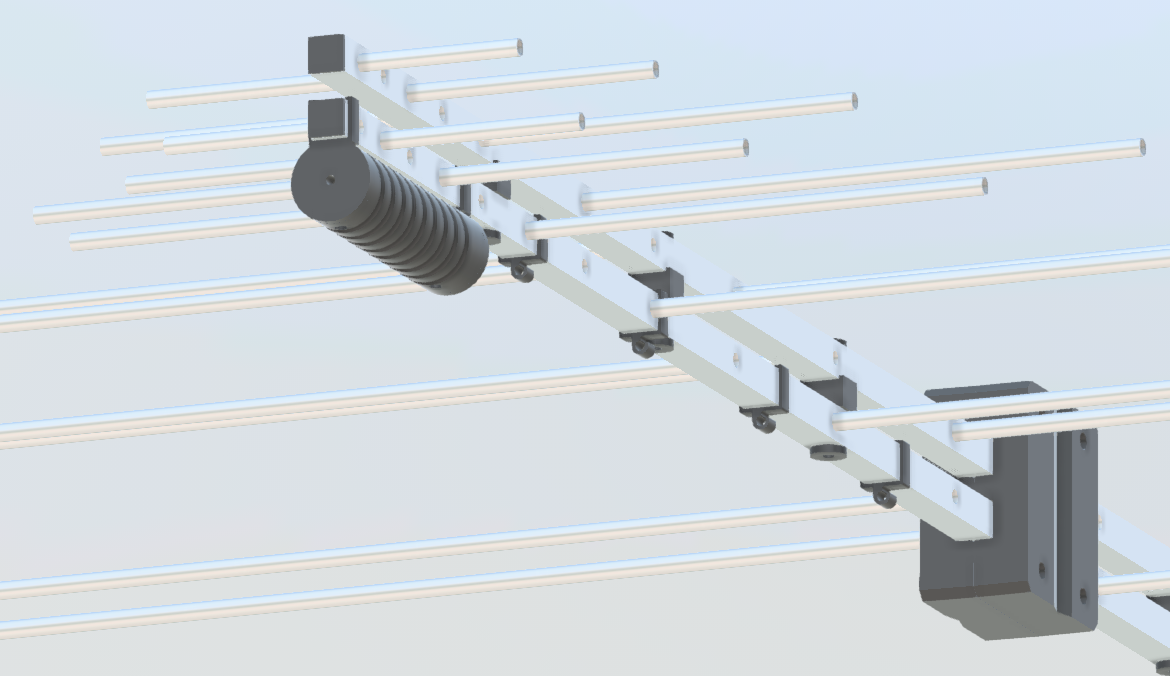
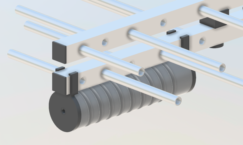
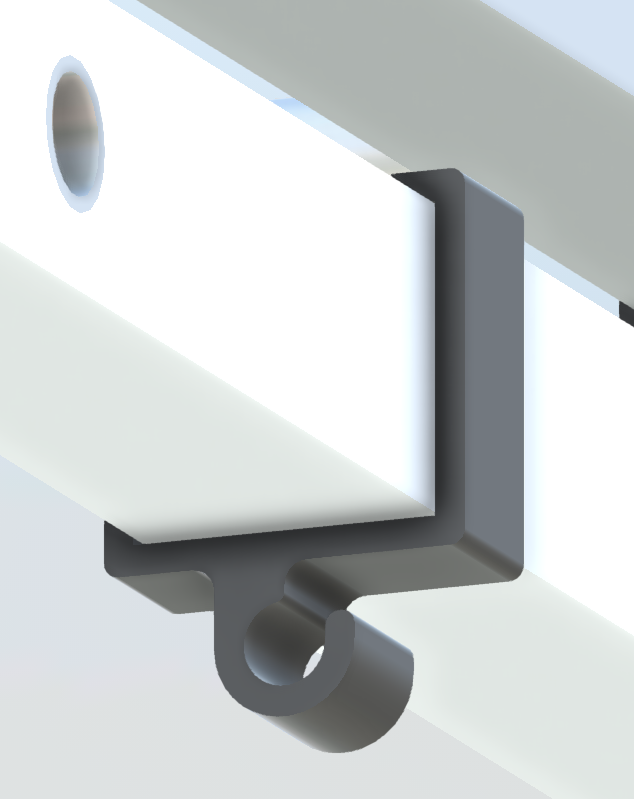
Boom Spacing Using the accurate square-conductor formula, the booms will be spaced at 35 mm center-to-center (15 mm gap). I’ll be 3D printing rigid PETG CF spacers to maintain this exact distance and provide electrical isolation.
Terminating Stub I’m extending the two booms by 765 mm behind the longest element (E1) and shorting them together at the rear with an aluminum plate. This method is mechanically robust, simple to build, and avoids the complications of a separate folded stub.
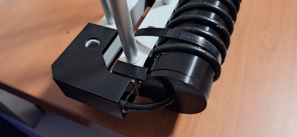
Feedpoint & Choke The antenna will be fed at the front with 50 Ω coax. For the wideband balun (critical for 50–450 MHz), I’ve chosen a 9-turn RG-58 coax choke wound on a custom 3D-printed 45 mm grooved former. This approach gives good common-mode rejection across the entire range without introducing narrow resonances that some ferrite solutions can have at the band edges.
Construction Materials
- Elements & Booms: 10 mm aluminum tube + 20×20 mm square aluminum tube
- All custom parts: 3D printed in PETG Carbon Fiber (spacers, choke former, boom-to-mast mount, etc.)
- Hardware: 100% stainless steel (bolts, screws, plates)
- Feedline: RG-58 for the choke + low-loss coax to the radio

What’s Next
Over the coming weeks I’ll be:
- Cutting and drilling the booms and elements
- Printing all the PETG CF components
- Assembling the antenna
- Testing with the VNA
Once it’s complete and mounted, I’ll write a detailed follow-up post covering lessons learned, build tips, SWR curves, and initial on-air performance.
I’m really looking forward to seeing how this wideband LPDA performs in practice. It should make a great all-in-one antenna for monitoring, contesting, and general ham radio use across VHF/UHF.
73, I’ll keep you updated as the build progresses!
Update 14/07
The build is done!
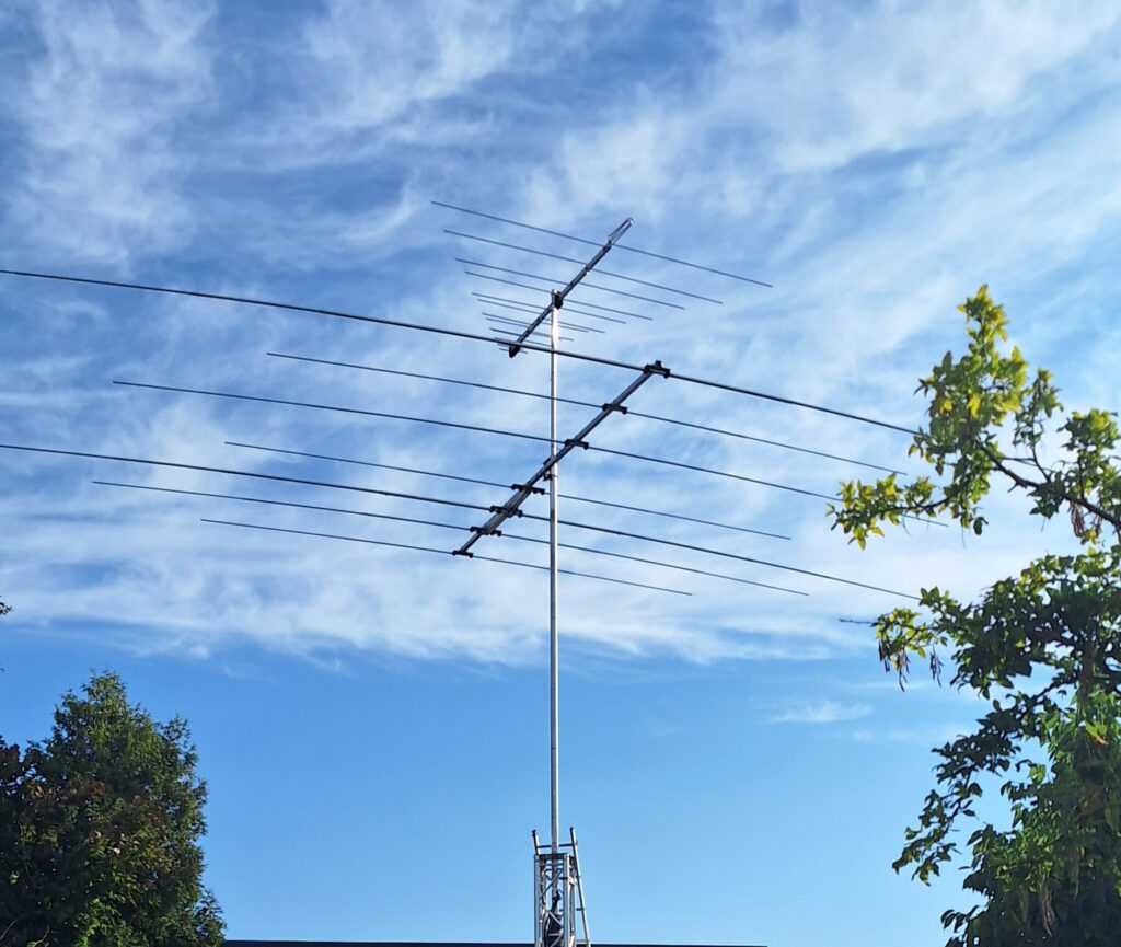



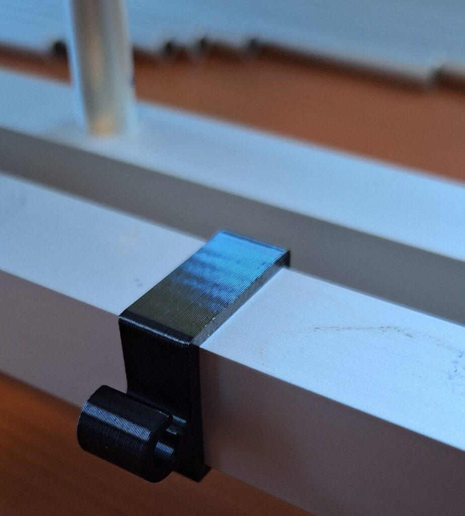
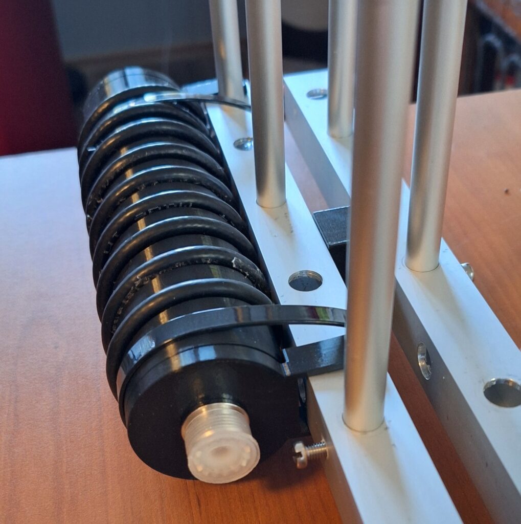
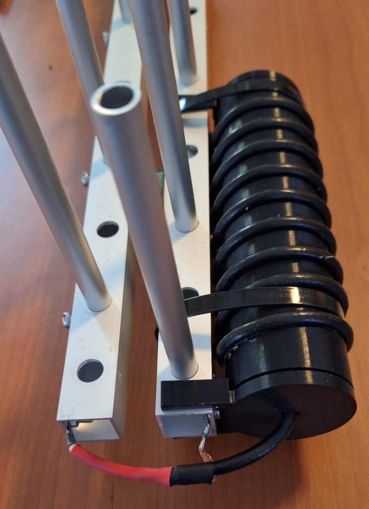
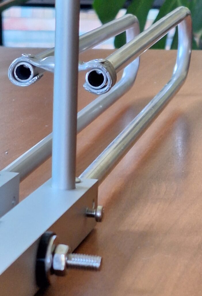

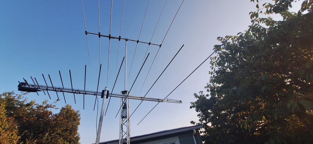
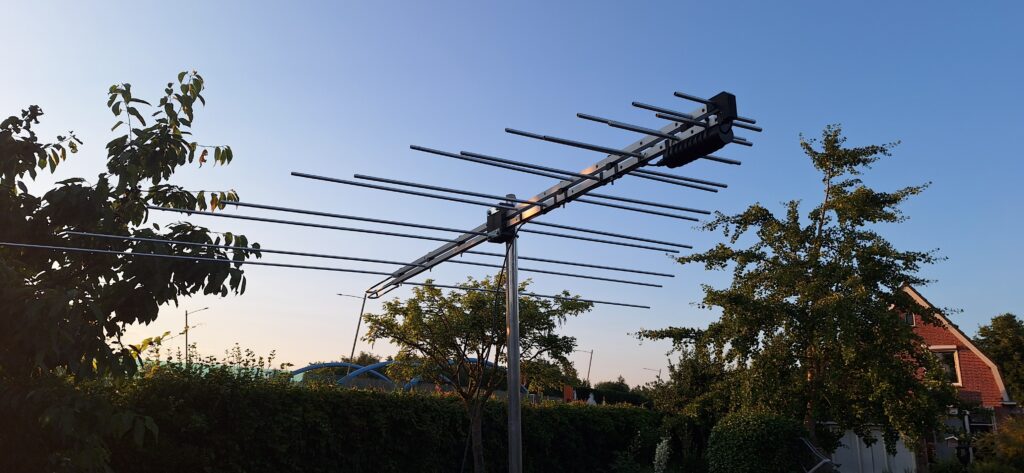
First impressions
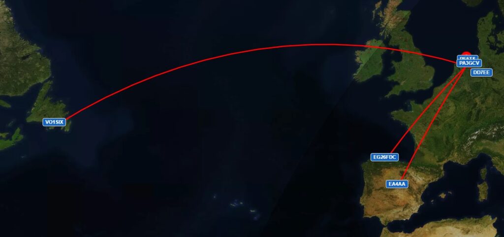
I didn’t know what to expect on 6m, so just winged it. Great surprise when I managed to QSO with Canada on SSB with 95 watts! I will be doing some further testing over the coming days.