

Finding the Most Efficient 49:1 Unun for my EFHW Antenna
I’ve been looking to get the most out of an End-Fed Half-Wave (EFHW) antenna, and in doing research I came across an interesting Youtube video from MM0OPX detailing quite a bit of research he has done in relation to toroids used for EFHW antennas.
My main goal was to ensure that the power is radiating out as a signal, not getting lost as heat, so having a good efficiency, especially on 40m and 80m! His research seems to point to a type 43 mix ferrite toroid that is smaller in diameter but thicker than the more common FT240-43 cores, in a 49:1 unun configuration.
I’ll try and walk you through my journey building the EFHW.
Note: I will be adding another blog post with some test results after some usage.
The build focuses on a single-winding auto-transformer style, which has proven to be more efficient and have lower insertion loss than older bifilar twist designs. This specific single-core unun is perfect for QRP or lower power operations, comfortably handling about 100 watts for digital modes and 200-300 watts for sideband.
My Parts List
Here is a list of the materials I used for the project:
Components:
- Toroid Core: One Fair-rite 2643251002 core. This is a type 43 mix material that is smaller in diameter but thicker than the more common FT240-43 cores, and it’s the key to this build’s high efficiency.
- Magnet Wire: Approximately 137 cm (54 inches) of 1.2 mm (16-gauge) enameled magnet wire. This is standard wire used in electric motors and generators.
- Capacitor: One 100 picofarad (pF) TDK capacitor. Using a quality brand like TDK is crucial. Tests have shown that generic capacitors can lead to enormous power loss, so don’t skimp here!.
- Connectors: An SO-239 connector for the coax feedline.
- Enclosure: A suitable project box to house the finished unun. I ended up 3d printing one myself.
Getting things done!
Step 1: Prepare the Wires
- I cut a 127 cm (50-inch) length of the enameled wire. This will be the main winding.
- I cut a separate 7 to 10 cm (3 to 4-inch) piece of the same wire. This will be the tap.
Step 2: Wind the Toroid Core This unun requires a total of 14 turns on the toroid core. The tap will be positioned at the second turn.
- Start winding the long end of the wire through the center of the toroid. It doesn’t matter which direction you wind.
- Continue winding until you have a total of 14 turns passing through the center of the toroid.
- Important: As you wind, keep the wires tight on the inside radius of the core and ensure they do not overlap in the center. The transformer’s function depends on the wire passing through the center of the core. The windings will naturally be spread out on the outer edge.
Step 3: Create the Tap Connection Point
- Locate the second winding. This is where the tap will be made.
- Using a sharp knife and needle-nose pliers, I scraped the enamel off a small section of the outer winding and bent the wire at the center of the winding section to form a small loop that sticks up. This loop is where I attach the tap wire.
- Take the shorter wire and scrape the enamel off one end. Bend this stripped end into a small loop.
- Mechanically connect the two loops. Hook the tap wire’s loop onto the main wire’s loop and crimp them together tightly. A solid mechanical connection is important, as solder alone isn’t strong enough.
- Solder the connection to ensure a perfect electrical bond. Heat the joint and let the solder flow through it.
Step 4: Connect the Capacitor and Final Leads
- The 100 pF capacitor needs to be connected across the primary winding (the first two turns). Scrape the insulation off the main wire at the starting point (ground lead) and off the tap wire (coax center lead) to prepare for soldering.
- Solder the capacitor leads securely to these two points.
- Here’s how the final connections work for this auto-transformer:
- Ground: The start of the winding (the end closest to the tap) connects to the shield of your SO-239 connector.
- Coax Center: The tap itself connects to the center pin of the SO-239.
- Antenna: The end of the 14-turn winding connects to your antenna wire.
Step 5: Finishing Touches
- Use zip ties to secure the windings firmly in place. This prevents them from moving around during use or testing.
- Trim the leads to the appropriate length for mounting inside the project box and connecting to the SO-239 and antenna terminal.
- Scrape the enamel off the ends of all three connection leads so they are ready for final soldering.
- Mount the completed unun inside the enclosure and make sure it is weather proof.
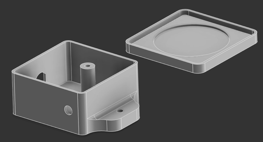
The EFHW enclosure as designed in Fusion 360 before printing.
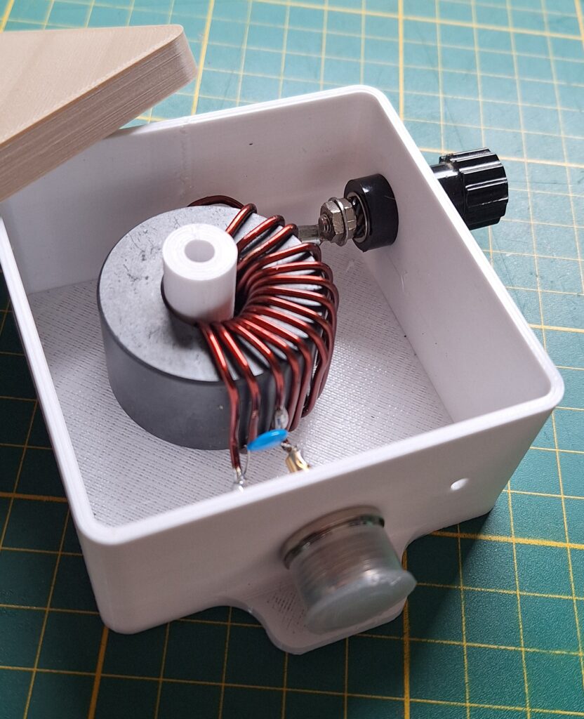
Here’s the fully assembled EFHW toroid in the 3d printed enclosure. For this I used ABS.
The first winding goes to the SO-239 ground connection. The tap on the second winding, going to the SO-239 center pin and the TDK capacitor are both visible.
I did not opt for an extra ground connector, but left a hole just in case.
The assembled EFHW feedpoint installed on a test location 2.5m from the ground. I attached roughly 21m of wire and trimmed it down to a suitable SWR for 40m. I was quite pleased to get a 1:1 match which showed no reflected power at the center of the band.
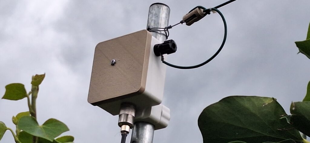
Did you know? When “trimming” the antenna wire length for SWR adjustments, you don’t have to cut the wire; simply fold it back on itself and tie it to the main line with zip ties. It’s important not to let the folded back section hang loose. Once you have the correct length, you can safely cut the wire.
I will be extending the antenna wire for 80m in the next phase of testing. Let’s first have some fun on 40m! Watch this space!