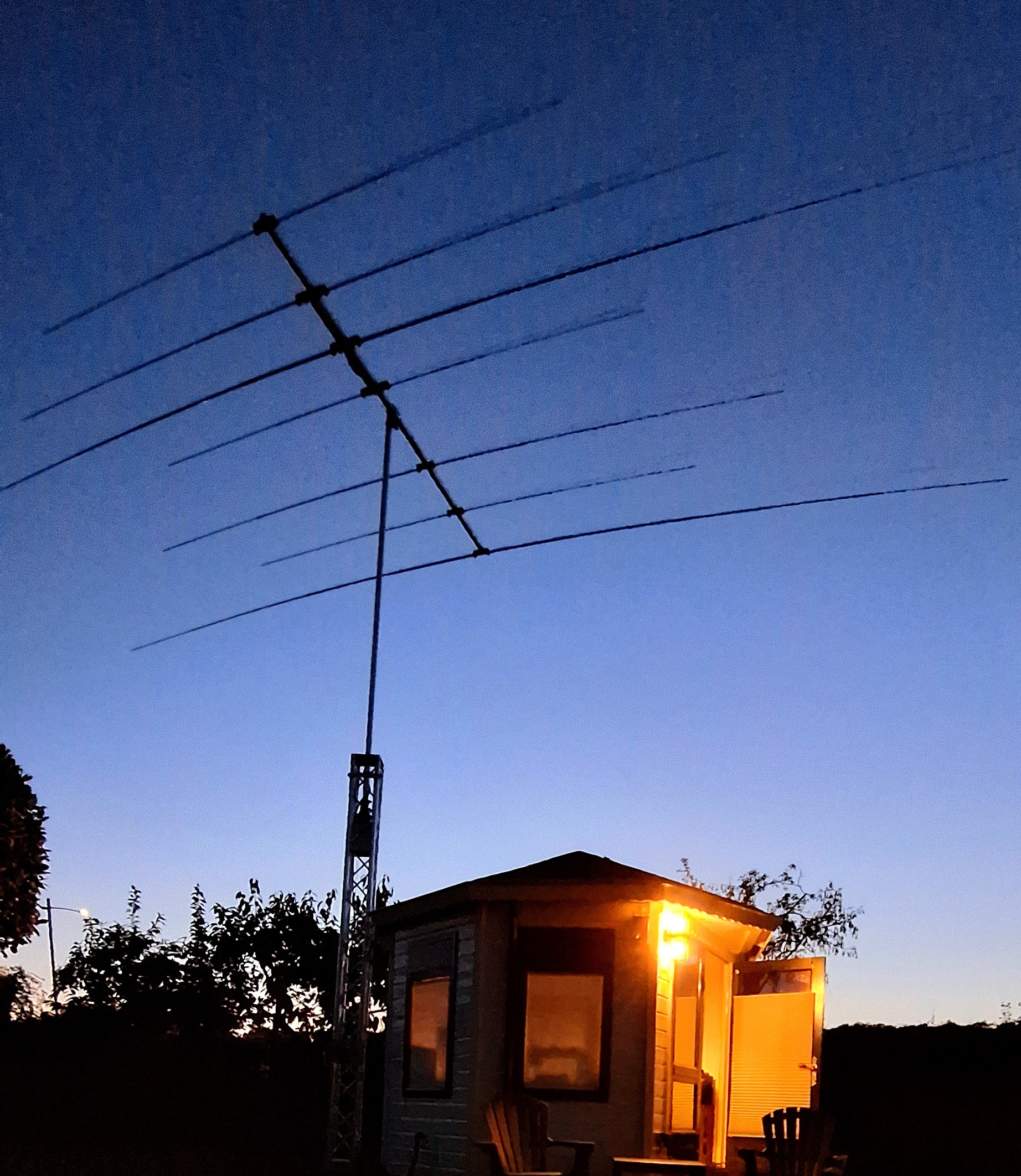
After giving the hobby a tiny 26-year break (yep, I said 26 years!), I figured it was time to dive back into the wonderful world of amateur radio. My true love? HF DX’ing, of course, so that’s where I naturally picked things up.
Now, The Netherlands is famous for many things, but I quickly got a reminder that one of those things is… regulation. Lots of it. Especially when it comes to putting up an antenna mast. So, long story short: the best I can do is a 7.5-meter mast right next to my shack.
Once I made peace with the fact that getting permission for anything taller would involve a ton of time, effort, and money, I set out to make the most of what I had. My mission? Find a solid directional antenna. With a bit of patience (and some luck!), I scored an Optibeam 7-element tri-band yagi. The OB7-3 is famous for its short boom, but even then, it’s a big antenna. With the windy conditions at my QTH, I wanted a crank-up mast/tower for peace of mind. The budget was tight, so I hunted for something second-hand—but came up empty.
So, thinking cap on, I decided to DIY it! The challenge: keeping costs low while making sure it was strong and reliable. Cue inspiration from the music industry—aluminum trusses! These are used on stage setups, come in various lengths, lightweight and are very strong. My plan was to have two mast sections: a top pole section mounted on the rotator, which slides inside the bottom section, a square truss. Both sections are 4 meters long, giving me a total height of roughly 7.5 meters when fully extended.
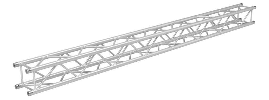
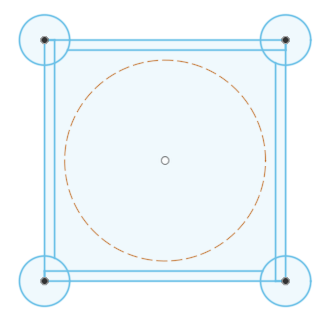
After loads of research i decided on a standard square FX34 model with inner diameter large enough to accomodate my Yaesu G-450XL rotator inside. It has 4 legs that are 50mm in diameter and have a 2mm wall thickness. The cross bracing is 20mm with also a 2mm wall thickness and is neatly welded to the center of the legs, so they do not interfere with anything sliding up & down the inside of the truss (my rotator!).
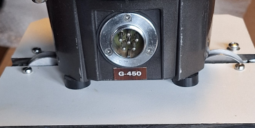
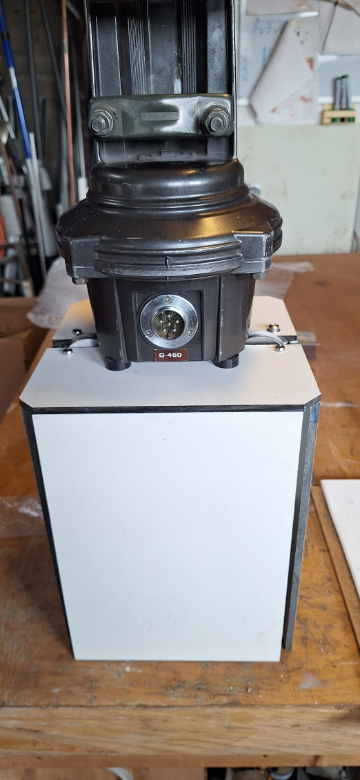
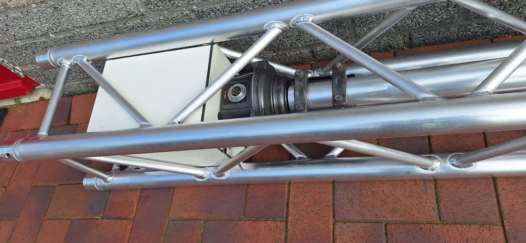
I next fabricated a box to mount the rotator on, making sure that there is enough clearance to slide up and down inside the truss. The bottom of the box is open so the coax and other cables hang down inside the truss. The material I used had to be strong en weather resistant. From a previous project, I had some 4mm High Density Polyetheen (HDPE) left. This was perfect for the job and would not damage the aluminium when moving up and down the truss.
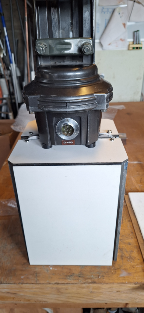

Above photo shows the box and rotator mounted inside the truss.

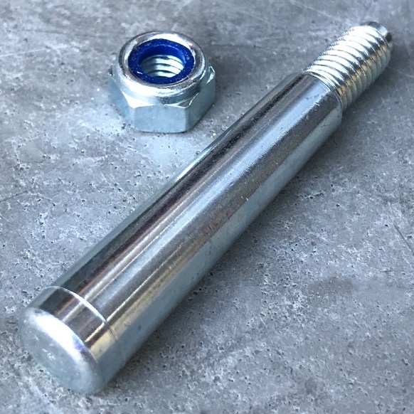
When purchasing the truss, I also purchased a matching base plate. This is constructed of solid 6mm aluminium and has perfect conical connectors to secure the truss legs.
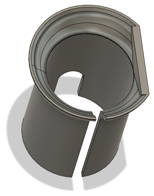
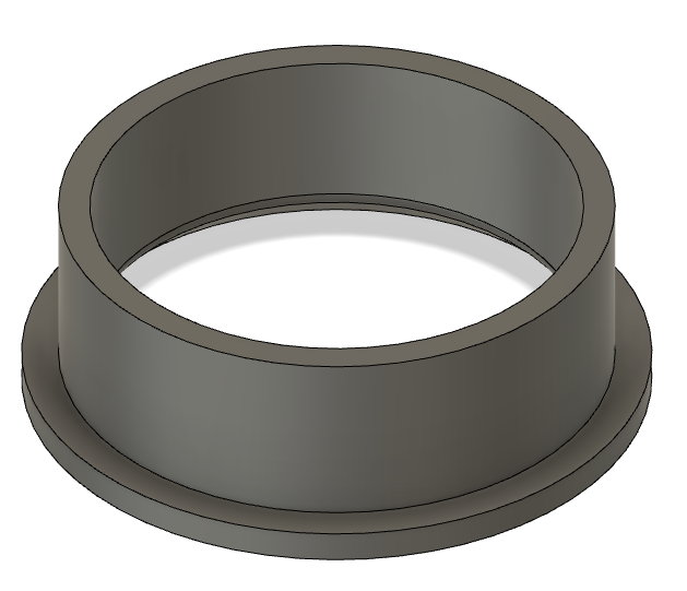
I fabricated a copy of the base plate, again from HDPE to function as a top plate with a hole in the middle large enough to accomodate the top section pole. This hole was also fitted with a 3d printed ABS protection guide ring in order not to damage the pole when sliding.
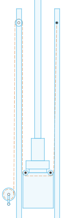
The rotator box also houses the two pulleys, which guide a steel cable which is part of the hoisting mechanism. The guide cable enters the box on on side, is feeded inside the box to the second pulley where it exits the box and up the tower.
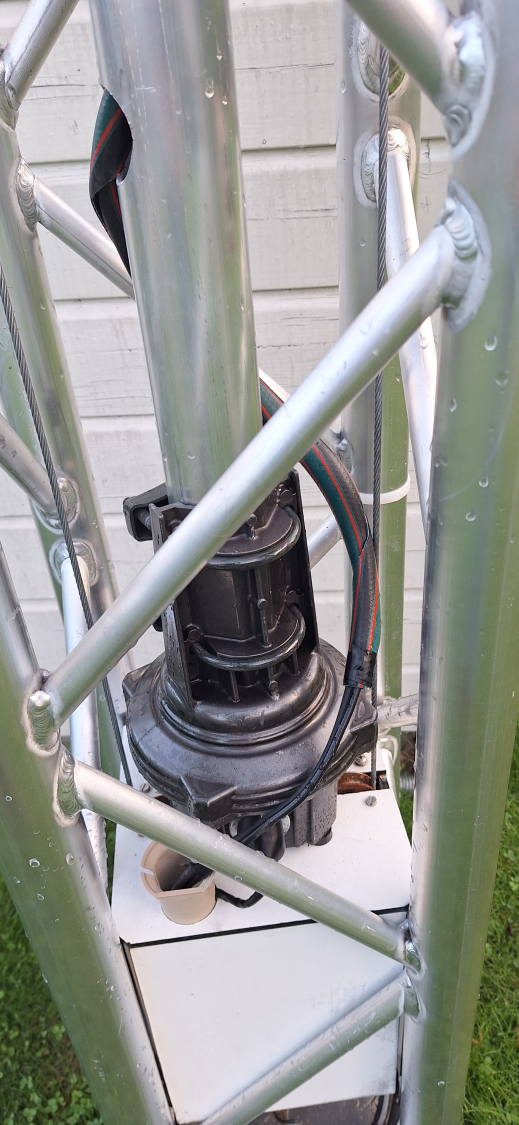
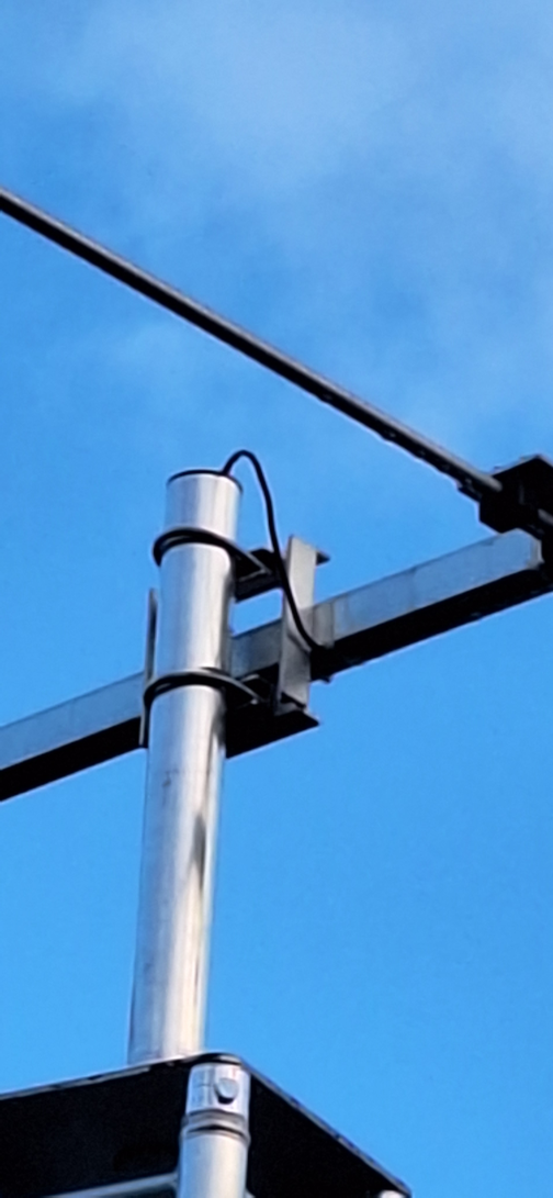
The top section is a 4 meter 70mm aluminium pole with a 2mm wall thickness. The bottom is attached to the rotator and the top to the antenna. The coax cable runs down inside the top section and exits via a hole in the pole just above the rotator mount. The coax cable then runs through a hole in the box, fittend with a 3d printed guide to allow the cable to easily slide in and out when the rotator turns. When turning the rotator, the cable is essintially coiled around the top section which works fine because the cable is in essence hangin loose towards the bottom of the tower. I wrappped this section of the cable in a protective sheeth made of garden hose.

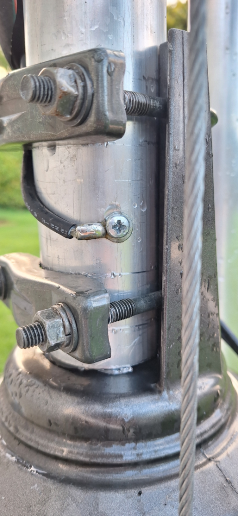
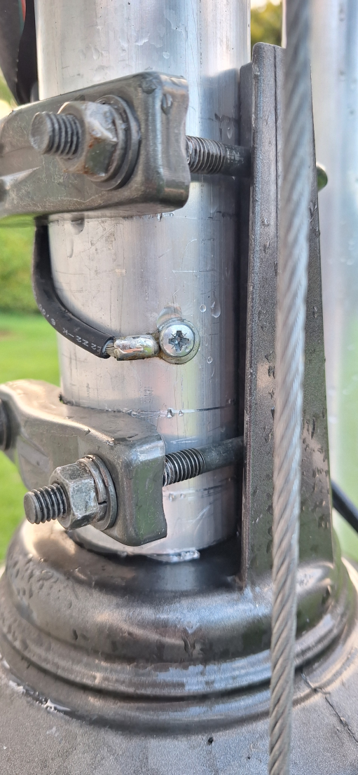
Analysing the construction, I realised that, due to the rotator and top section mounted on the box, there was no electrical conductivity between ground (bottom section of the tower) and the top section (pipe mast). This would mean that the antenna is electrically grounded through only the coax cable outer sheeth! This was easily fixed by attaching a thick grounding cable to the top section pole and running this through the same hole to the bottom of the tower and then to the grounding rod.
The rotator control cable runs trough the same hole and down the tower in the same fashion. This results in 3 cables tied togerther as one, running down the inside of the tower when extended, and coiling up neatly on the base plate when the mast is retracted.


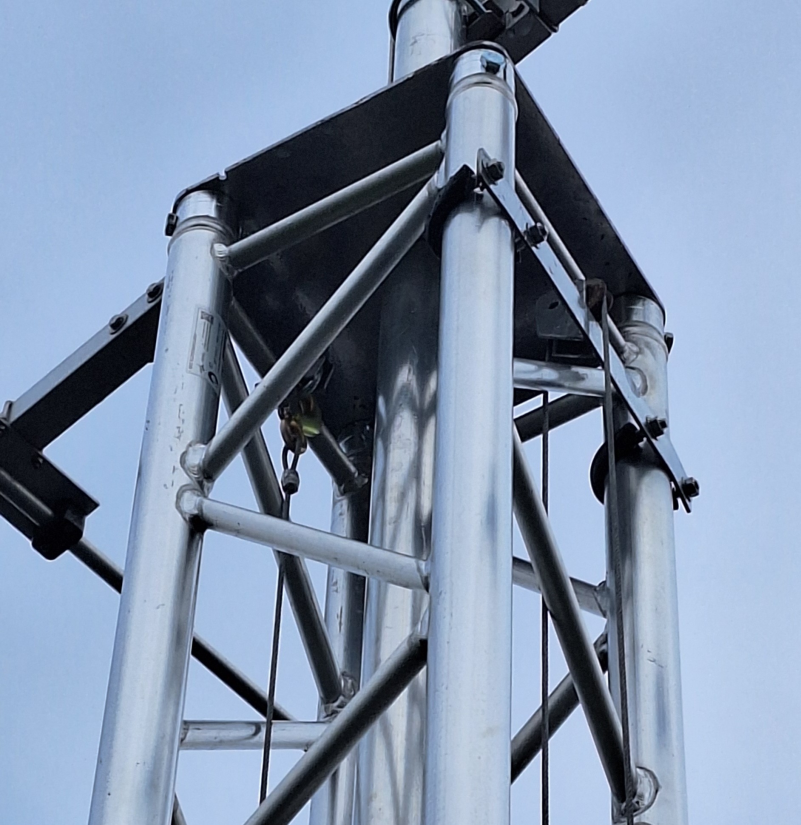
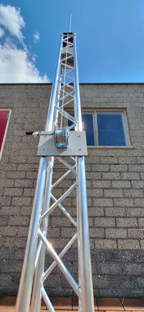


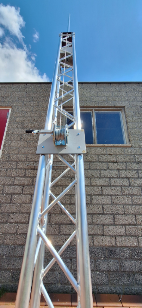
The hoisting system is made up of a winch mounted low on the bottom section of the tower. The cable runs up the bottom section to a pulley and back down under the rotator box and up again to be fastened on the top opposite side of the tower.
In conclusion I’m quite happy with the result. Completely lowered the antenna is at an easy to reach height, which makes maintenance and fitting some exra antenna’s easy. Fully extracted the antenna sits at 7,5 meters, which up till now has given exteremely good results, both in relation to SWR and performance.